Power-plant mounting
All power plants, with the few exceptions, are mounted in the forward end of the frame. The transmission is considered part of the power plant, since it governs or controls the ratio of speed and power which may be delivered to the rear axle. The engine drives the transmission, and the transmission turns the propeller shaft. |
V-8 power plant (Ford V-8 engine
and accessories).
|
The most favoured method is to build engine, clutch, and transmission together as a unit, and mount the unit power plant in the car frame in a manner calculated to prevent engine vibrations being transmitted to the car interior. Rubber-lined mounting blocks, are used to check engine vibration.
For many years either three- or four-point metallic contact mounting was used for the unit, power plant, both being popular with the manufacturers. The later use of the rubber engine-mounting blocks reduced the amount of vibration carried to the driving compartment.
Chrysler engineers learned that by mounting an engine at two points, so that the centre of mass or centre of gravity was approximately on a line between the two bearings (one well up on the front of the engine and the other under the transmission case), engine vibration could be still further reduced. The rocking or torque reaction of the engine under load was first absorbed by a leaf spring but later this spring was replaced by rubber blocks which were found more effective. There are many variations of power-plant mounting, most of which make use of some form of rubber mountings.
Just as the units of the chassis were considered, it is desired to separate and study the functions of the units composing the power plant on this page. Next, the individual units going into an engine are studied, and in the individual parts of the various other units of the power plant are discussed in detail. On this page, it is desired to familiarize with the names and locations of the various units going into the make-up of a complete power plant. The duties falling to the lot of each accessory or unit will be discussed briefly.
Engine
The water pump and oil pump appear on the left side of the engine, and are considered a definite part of the engine. A fan-drive pulley appears on the forward end of the pump shaft. A fan mounting bracket is provided. |
 |
Nask engine
|
Chevrolet engine
|
When the starting-motor manufacturer builds his equipment, it is built according to the same specifications, and a fit is thus assured. The manifold is a part of the engine, but the carburetor is an accessory. The intake and exhaust manifolds are cast together in some instances. A flange is left at the centre of the manifold. This flange is machined to allow the carburetor to be fitted to it.
Carburettors are made in varying sizes and certain size flanges are provided for the specified carburetor sizes. The car manufacturer may then fit a carburetor of the size desired and of the make which he may select from those offered. Other fittings and accessories are mounted on the engine where the car manufacturer may desire. The engine manufacturer usually provides certain bosses at advantageous points, and the car builder utilizes them at his discretion.
Where the car manufacturer builds his own engines, the practice will vary slightly. Only those mountings are provided which the designee knows are to be used., It is very rare that the engine accessories are built by the car manufacturer ; hence all these are designed with certain fittings known as S.A.E. specifications. Members of the Society of Automotive Engineers (S.A.E.) have agreed on these specifications, and parts will fit when machined according to them. This greatly reduces the cost of production, and car owners as well as manufacturers benefit by it.
Carburetor

An engine, such as is used in automobile service, is termed an internal-combustion engine. This means that the fuel is burned within it. The point where the fuel is burned is called the combustion chamber. This space is above the piston in the cylinder head and around the valves, and naturally includes that portion of the cylinder exposed as the piston is driven down.
The fuel used in engines is, for the most part, gasoline or similar fuel. The burning process is ordinarily termed firing or exploding the gas. The fuel, that is, the gasoline, in order to be burned or "exploded" within the combustion space, must first be passed through the carburetor where it is mixed with air. Next, it must be drawn into the combustion space, and then it must be compressed after which it is fired by the electric spark.
The function of the carburetor is to mix the fuel and air. In order to mix the gasoline with the air, the gasoline must be sprayed into the air which is rushing through the carburetor on its way into the engine. The early carburettors were called mixing valves.
Gasoline is furnished the carburetor from the main supply tank by means of a fuel pump, a vacuum tank, gravity feed from the main supply tank, or air pressure. Carburetor engineers spend much time designing and testing their product for motor-car manufacturers.
The demands placed on carburettors vary with load, bore and stroke of the engine, climatic conditions, rear-axle-gear ratios, and a multitude of other details. Variation in fuel is, of course, a vital consideration. The principles of carburetor construction will be discussed at a later point, but at this time it is well to fix its function clearly in mind. The carburetor, by aid of the suction of the engine, takes raw fuel, converts it into a spray of vapour, and mixes it with a charge of air for the cylinders of the car.
The mixture is called a fuel charge. Maintaining the proper proportions of fuel and air at all engine speeds is the task of the carburetor. If this is not done, the engine fails to operate satisfactorily. Carburetors may be either updraft, in which case the incoming air passes up, through it, or downdraft (air passing down).
Timer-distributor and coil

It is the function of the ignition set to deliver a spark to the spark plug at the approximate moment when the compression is greatest. All timer-distributors are manufactured to S.A.E. specifications. The car manufacturer selects the equipment which he desires, or he may have the electrical-equipment factory build it after a specified design.
An ignition set may be either self-contained as in the case of the high-tension magneto used on some busses, trucks, marine engines, racers, and aircraft engines, or it may be composed of several units. Every ignition set has three major parts. These are the timer, the distributor, and the coil .
Battery ignition depends on the generator and battery for current. High-tension magnetos generate their own current. Almost all passenger cars depend on the manufacturers of batter y-ignition equipment for their ignition sets. The theory of ignition is discussed later.
In brief, it is as follows: The ignition coil draws current at low voltage from the battery. This current is stepped up to high voltage in the coil when the timer breaker points open. The high-tension current (spark) is carried to the proper plug by the cable from the distributor. Thus, its task of firing the charge of fuel in the cylinder is performed in time with the engine rotation.
Spark plugs

The purpose of the spark plug is to receive the high.. tension spark or current from the distributor (through the spark-plug cable), and conduct it to the combustion space, where it fires the charge as it jumps the air gap of the plug. It must be made most carefully in order not to break down in the intense heat of the exploded gases. Ordinarily, one plug per cylinder is used by the manufacturer, but two plugs may be used. When more than one plug is used in a cylinder, it is with the idea of preventing failure and also securing quicker ignition.
Generator

Passenger cars are dependent on the storage battery for their ignition and lighting as well as electric cranking. The battery would quickly be exhausted were it not for the generator which is constantly building up or charging the battery when the engine is operating above an idling speed. Different methods are used to drive the generator. Unlike the timer-distributor, it is not necessary to drive the generator at a definite speed relation with the engine.
Belt drive is popular and quite satisfactory. The pump may be connected to the shaft by any one of several means. Special flexible couplings are used and, in a number of instances, rubber hose is clipped to the ends of the accessory and generator shafts, thus giving a quiet and flexible drive. The functions, then, of the generator are to keep the battery charged and assist in supplying current for the lighting of the lamps of the car and furnishing current for ignition.
Starting motor

Hand cranking was for many years a factor in limiting the use of passenger automobiles. Special spring starting devices, gas starters, and air starters were designed to relieve the driver of this arduous and dangerous task. When Mr. Chas. F. Kettering, Vice-President of General Motors, in Charge of Research, invented and perfected the system of electric cranking of automobiles, he performed a wonderful service for both car manufacturers and the general public.
Starting motors are designed to turn the engine over at speeds in excess of those possible by hand cranking. They are connected to the engine while cranking it, and then are automatically disengaged when the engine starts to operate under its own power. Starting motors, although small, are assigned heavy duties.
The amount of current they draw is very great. Operating them quickly exhausts the battery. The generator requires about fifty times as long to recharge a battery as is required to discharge it in normal starting service. The function of the starting motor is to crank the engine until it has drawn in gas and compressed it, at which time the ignition-distributor delivers a spark to fire the charge, and the engine operates under its own power.
The starting motor of a passenger automobile operates for a very short period of time and at very infrequent intervals. The "starters" are now so well built that failure occurs only very rarely.
Clutch

There are a number of types of clutches. Cone clutches were very popular at one time. Disk or multiple-plate clutches were used in many passenger vehicles. Single-plate clutches for light cars and double-plate clutches for the heavier cars are in general use.
Clutches are provided with a clutch-pressure plate which moves or is made to turn with the flywheel at all times. A plate is fastened to the clutch shaft, and this connects with the transmission shaft. When the clutch is held in the "out" position, the clutch-pressure plate on the flywheel is free to turn with it, but does not cause the plate fastened to the clutch shaft to turn.
When "in," the springs in the clutch-pressure plate throw the plates together and hold them that way. The friction material on the driven plate engages the plain faces of the clutch-pressure plate and the flywheel, and causes it (the driven clutch plate) to turn. Clutches must give a smooth pick-up of the load, and must release the load quickly when the clutch pedal is depressed. They must hold positively under all conditions of load, and yet must be free of grabbing or jerking.
The hydraulic drive (fluid flywheel) eliminates all jerking. With its use, much gear-shifting is eliminated since the load may be picked up in any speed.
Transmission
The connection of the transmission with the power plant was discussed at the first part of this chapter. Transmissions are made by manufacturers ,of cars in many instances ; but very often they are built by factories which have had long experience in building gears for this special service.
Transmission gears are subject to as severe use as, and worse abuse than, any other part of the automobile with the possible exception of the clutch. However, these two items are used in connection with each other, and each must stand much abuse from inexperienced and incompetent drivers. The transmission gears are the only gears about the motor car which are not as a rule in constant mesh. Gear shifting means demising and meshing of the teeth of the driving and driven gears except where shifting dogs or dog clutches are used.
In case of unsuccessful shifts, or shifts which are only partially completed before the clutch is let in, the teeth of the transmission gears are subject to abuse. Clashing and grinding gears is abuse. A driver, who is untrained in shifting, and who fails to understand or heed instruction, will ruin the best gears it is possible to make. In his hands, gears, which should give service for the life of the car, are ruined in a few thousand miles. As designed by the builders, the transmission gears are amply strong, if not abused.
Conventional practice specifies the use of the sliding gear or change gear as a means of securing changes of car speeds. Reverse drive also is secured through gear changes in the gear box or transmission case. Differences in construction details in the transmission are treated elsewhere.
Fan

Engines are provided with fans, to draw the air through the radiator when the engine is operating. Heat from the engine must be passed off into the air. The water in the engine water jacket carries it to the radiator, and the air passing through the radiator conducts the heat out of the fins and tubes. Fans are usually made up by shops which cater to the car manufacturers, by producing some of the smaller parts for them. Belts are used as a rule for fan drive. Adjustment of the fan bracket is provided in order that the fan belt may be kept at proper tension.
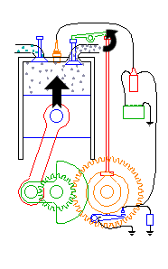
Engine accessories

Figure on top of this page illustrates a number of the usual engine accessories. Most engines are fitted with an air cleaner which may also be designed as a flashback screen or fire preventer or an intake-roar silencer. The carburetor on this engine is downdraft.
The exhaust manifold has a centre outlet for tail-pipe connection. The intake manifold has a section interlocking the exhaust manifold so as to receive heat there from. The oil pump is driven from the camshaft and is easy of access from the side of the engine. The oil cleaner is attached to the engine near the oil pump and just to the rear of the fuel pump which is driven by the engine from the camshaft. The fan is mounted on the water-pump shaft and is belt-driven.


